Friday 3 January 2014

Concrete pour!!


 The outer former has been assembled. I've used right angle metal bracket to secure the former down to the sheet of mdf.

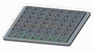
You can see the 3d printed feature housed in the walls of the former.


The silicone cast features have been glued in position.  In hindsight I'd have perhaps liked these to not be permanently fixed.


The inner core has been screwed in place.  The outer walls of the core will remain insitu.  The blue foam is a precautionary measure in case the acrylic/glue joint fail.


I've decided to use latex cement. The walls of the speaker in some places are less than 10mm thick and the features are incredibly intricate.  This would cause significant problems when using conventional concrete.  Latex cement is used typically for self levelling floors.  The mix is very wet, and so should run freely in to the mould, preventing any honeycombing to the finished surface.  Traditionally mould oil or release agent is applied to the surface of the mould to prevent it from adhering to the concrete.  However, because this is only bought by the gallon, I've decided to try traditional motor oil.


When pouring the concrete I took great care to pour in layers.  Unfortunately, I didn't have access to a vibrating plate or rod to reduce the risk of trapped air.  However, I did tamp the concrete and gently tap the sides of the mould.

As seen on the picture to the right, some concrete did flow beneath the mould.  I didn't anticipate this, for the next pour I'll silicon seal the joint to prevent loss of material.


The self levelling concrete requires no floating to finish.  It takes 2-4 hours to set.  However, I'll leave it 12 hours.  This should be sufficient time for the concrete to harden.  Concrete can cure for 28+ days, but, if left in the mould this long, the potential for the concrete to adhere to the mould increases and so the risk of damage during removal.


Tuesday 10 December 2013

CAM starts

 
CAM
 
Today I formatted my CREO drawings to be compatible with the CNC machines.  The outer former has been grouped together to form one cutting piece as oppose to being cut singularly.  This will reduce set up time, which saves money and reduces carbon emissions. 
 
The material I've chosen to use is model board.  This will ensure a smooth finish to the surface of the formers.  Some light sanding may be required prior to use.  Sealant or wrap to also reduce chemical attack from the concrete.


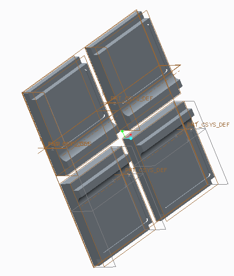
Below is the feature which will be attached to the mould.  I'll need four of these pieces to complete the mould.  Due to the 3D printer being costly, I've decided to 3D print one piece and make a silicone cast to duplicate the remainder.


The feature has been shelled (as seen below).  This again reduces time, money and carbon emissions.  Throughout this project I've been mindful of cost and energy efficiency.


Monday 9 December 2013

Feature housed in body former

 
Feature design to body


This is the completed outer former.  The feature will be 3D printed and then duplicated by forming and casting in either silicon or resin.  The feature is interchangeable which is beneficial in manufacture as the mould can be changed, utilising the outer former mould for other designs.

The outer former is now complete and ready for manufacture.

I've decided to change my inner former from polystyrene to a cast in situ former made of acrylic.  Details to follow.


Further CAD development


CAD DEVELOPMENT


I've revised the design of my external former.  The former is now made from four interlocking pieces.  It will still be CNC machined. 
 
 
 In order to enable a feature to be applied to the face of the body of the speaker the former has to break apart.  This will ensure the former comes free from the concrete.  The feature will be added to the internal face.
 This method greatly improves the ease of assembly and disassembly during manufacture.  These pieces would ideally be made of plastic, however, for this demonstration I will use jelatong.  The former will be lined with thin plastic sheeting, this will ensure a smooth, flat finish.

Sunday 8 December 2013

Grille

DESIGN DEVELOPMENT
 
I had originally designed the speaker body to be smooth and the grill to be the main feature.  However, after designing and assembling on CREO I've decided to now have this feature (or a similar design) cast in to the concrete.  In order to do this I'll have to redesign the former.


Checking assembly prior to manufacture


 The outer former will be routed from two pieces of jelatong.  It will then be lined with card. 
 The outer former will close to form the outer shell surface. This surface will be seen, and so the finish is important.  The concrete will need to be poured and cured correctly to obtain a good quality finish.
 The outer shell will lock in to place on the base plate.  The base plate will have to be level and will act as the working surface.  All the components will have to be oiled prior to the pour to avoid suction.
I've checked all of the components for fit.  The components assemble correctly thus preventing wastage in manufacture and preventing a poor finish to the concrete.


The next stage is to make the components using CNC machinery.


Next steps:

1)  Consider finish to concrete.
2)  Concrete mix properties
3)  Complete grille design